Slope Deflection Method for Continuous Beams
Civil - Structural Analysis - Slope Deflection Method
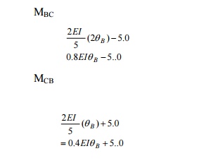
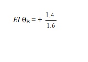
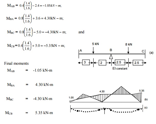
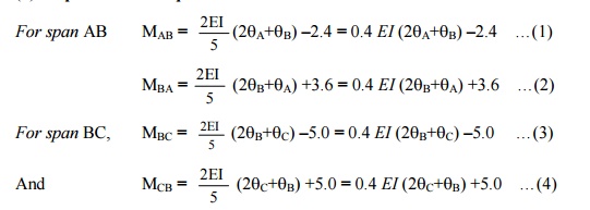
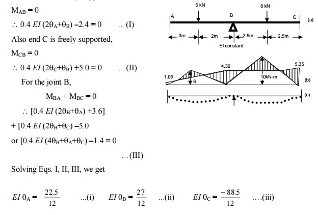
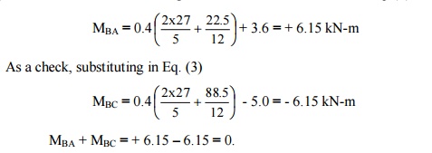
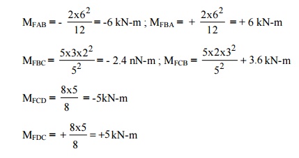
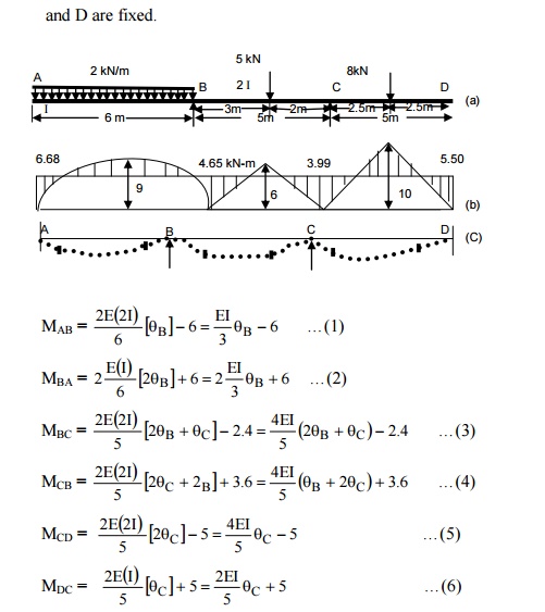
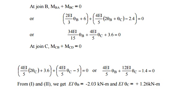
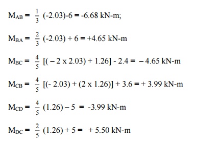
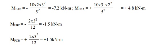
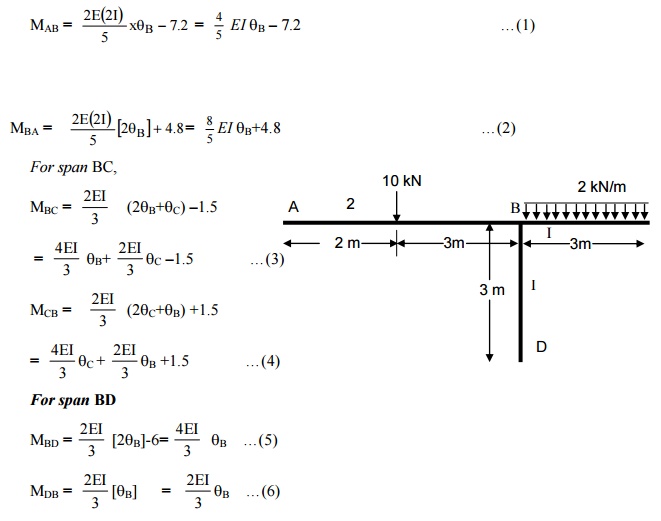
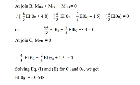
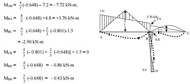
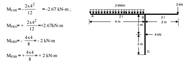
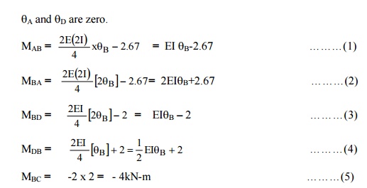
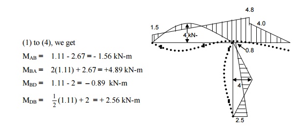
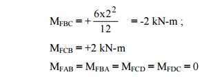
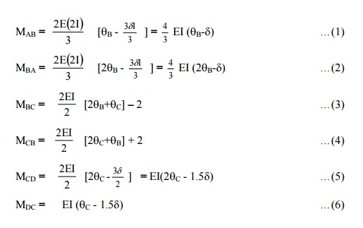
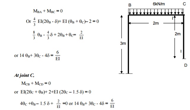
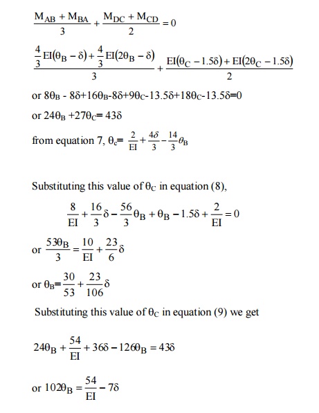
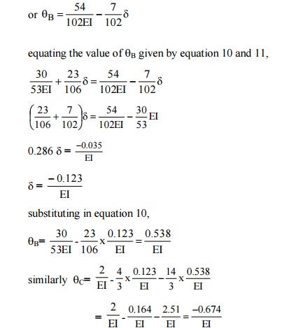
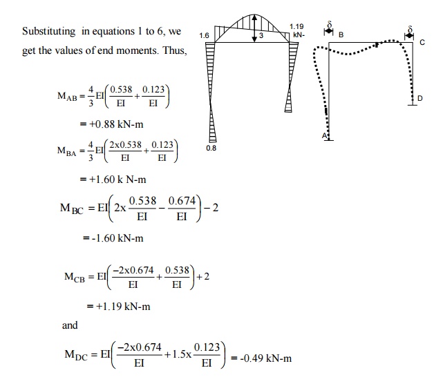
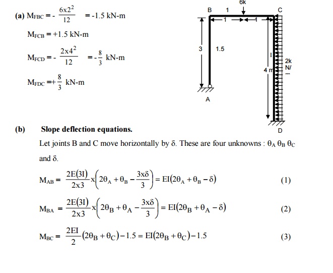
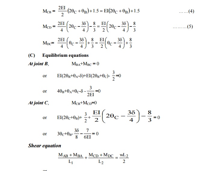
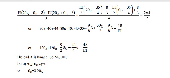
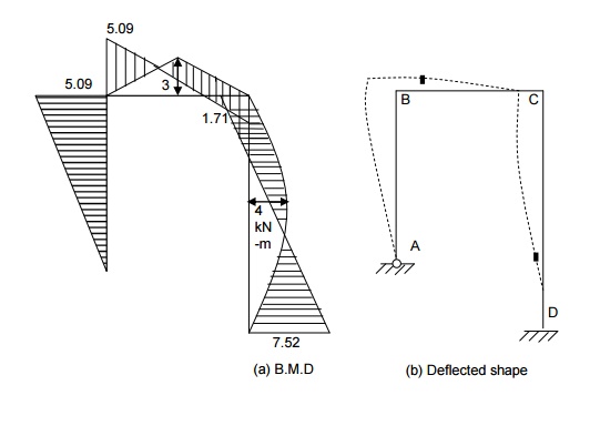
SLOPE DEFLECTION METHOD (1). A beam ABC, 10m long, fixed at ends A and B is continuous over joint B and is loaded as shown in Fig. Using the slope deflection method, compute the end moments and plot the bending moment diagram. Also, sketch the deflected shape of the beam. The beam has constant EI for both the spans. Solution. (a) Fixed end moments Treating each span as a fixed beam, the fixed end moments are as follows: (b) Slope deflection equations The end rotations q A and q C are zero since the beam is fixed at A and C. hence there is only o For span AB, For span BC , (c) Equilibrium equation Since there is only one un known, i.e. q B, one equilibrium equation is sufficient. For the joint B, we have MBA + MBC = 0 \ (0.8 EI q B + 3.6) + (0.8 EI q B + 5.0) = 0 1.6 EI q B = 1.4 The plus sign indicates that q B is positive (i.e. rotation of tangent at B is clockwise). (d) Final moments Substituting the values of EI q B in Eqa. (1) to (4), we get (2) A beam ABC, 10m long, hinged at ends A and B is continuous over joint B and is loaded as shown in Fig. Using the slope deflection method, compute the end moments and plot the bending moment diagram. Also, sketch the deflected shape of the beam. The beam has constant EI for both the spans. SOLUTIONS (a) Fixed end moments These are the same as calculated in the previous problem: MFAB = -2.4 KN-m ; MFBA = +3.6 KN-m MFBC = -5.0 KN-m ; MFCB = +5.0 KN-m (b) Slope deflection equations. (c) Equilibrium equations Since end A is freely supported, (d) Final moments : Substituting the values of EI q A and EI q B inEq. (2), we get The bending moment diagram and the deflected shape of the beam are shown in the Fig. Note. The beam is statically indeterminate to single degree only. This problem has also been solved by the moment distribution method (example 10.2) treating the moment at B as unknown. However, in the4 slope- deflection method, the slope or rotations are taken as unknowns, and due to this the problem involves three unknown rotations q A , q B and q C . hence the method of slope deflection is not recommended for such a problem. (3) A continuous beam ABCD consists of three spans and is loaded as shown in fig. ends A and D are fixed. Determine the bending moments at the supports and plot the bending moment diagram . a)Fixed end moments (b) Slope deflection equation q A and q D are zero since ends A and D are fixed. (c) Equilibrium equations At join B, MBA + MBC = 0 At join C, MCB + MCD = 0 From (I) and (II), we get EI q B = -2.03 kN-m and EI q C = + 1.26kN-m (d) Final moments Substituting this values in Eqs. (1) to (6), we get The bending moment diagram and the deflected shape are shown in Figure. 4) A continuous beam ABC is supported on an elastic column BD and is loaded as shown in figure . Treating joint B as rigid, analyze the frame and plot the bending moment diagram and the deflected shape of the structure. (a)Fixed end moments MFBD = MFDB = 0 (b)Slope deflection equations. The slopes q A and q D are zero since ends A and D are fixed. For span AB (c) Equilibrium equations At join B, MBA + MBC + MBD = 0 (d) Final moments Substituting this values in Eqs. (1) to (6), we get The bending moment diagram and the deflected shape are shown in Figure. (5) Analyze the rigid frame shown in figure (a) Fixed end moments (b) Slope deflection equations. (c) Equilibrium equations For the equilibrium joint B, MBA + MBD + MBC = 0 \ (2EI q B + 2.67) + (EI q B -2) + (-4) = 0 3EI q B = 3.33 EI q B = 1.11 (d) Final moments Substituting this value of EI q B in Eqs. (1) to (4), we get The bending moment diagram and The deflected shapes are shown in Figure. (6) A portal frame ABCD is fixed at A and D, and has rigid joints at B and C. The column AB is 3m long. The beam BC is 2m long, and is loaded with uniformly distributed load of intensity 6 kN/m. The moment of inertia is 2.1 and that of BC and CD is I (Fig). Plot B.M. diagram and sketch the deflected shape of the frame . (a) Fixed end moments Let the joints B and C move horizontally by d (b)Slope deflection equations. (c) Equilibrium equations. At joint B, d )Shear equation e) Final moments (7) A portal frame ABCD is hinged at A and fixed at D and has stiff joints at B and C. the loading is as shown in figure. Draw the bending moment diagram and deflected shape of the frame. 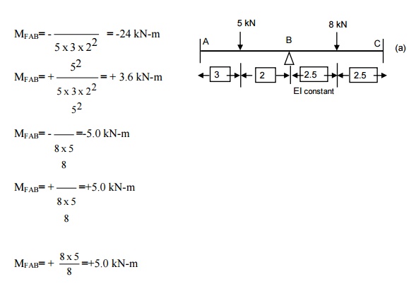
 ne unknown, q B . the ends do not settle and hence d for each span is zero. Let us assume q B to be positive. The result will indicate the correct sign. The slope deflection equations are as follows:
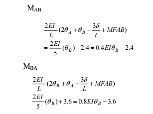
Study Material, Lecturing Notes, Assignment, Reference, Wiki description explanation, brief detail
Civil : Structural Analysis : Slope Deflection Method : Solved Problems: Slope Deflection Method- Structural Analysis |
Source: https://www.brainkart.com/article/Solved-Problems--Slope-Deflection-Method--Structural-Analysis_4578/
0 Response to "Slope Deflection Method for Continuous Beams"
Publicar un comentario